Each month in our Street Trucks magazine advertisement, we feature three photos submitted by our social media fans.
Here is your chance to get in on the action:
https://photovotes.pgtb.me/SSwtn1

Friday, February 26, 2016
Monday, February 15, 2016
What is BUMPSTEER?
Bumpsteer is something that some do not know much about or complain about. It not uncommon for customer who have installed lowering control arms or drop spindles to complain about bump steer. In this post we will provide you information to better understand what bumpsteer is and how it work.
The short story here is that excessive bump steer increases tire wear and makes the vehicle more difficult to handle on rough roads.

The short story here is that excessive bump steer increases tire wear and makes the vehicle more difficult to handle on rough roads.
What is bump-steer?Bump steer is when the front wheels move up and down, we want the front wheels to maintain a particular direction. It's most important for the wheels to have minimal bump when negotiating turns. There are certain elements of the construction of the front end components that will make this happen.The angles of the upper and lower control arms, meaning a line extending through the center of rotation of the ball joints and inner mounts of each arm, intersect at a point we call the instant center (IC). This is one of the components used to determine the moment center location. In order to have near zero bumpsteer, the intended goal, we need to have the tie rods on each side point toward the IC for its side. This is one of two criteria for near zero B/S.The other thing we need is for the tie rod to be a specific length. That length must be equal to the distance formed by 1) a line extending through the centers of rotation of the tie-rod ends, and 2) the tie-rod line intersection with a) lines extending through both the upper and lower ball joints, and b) the plane that passes through the inner chassis mounts. This can get a little complicated because although the ball joints do form a single line, the chassis mounts form a plane because of the front and rear mounts.So, the inner tie-rod intersection point is where the tie-rod line intersects the plane of the inner mounts and the outer line intersection point is where it intersects the ball joint line. A three dimensional geometry program can simulate this very well, but most of us don't have the luxury of owning and knowing how to operate one of those. If so, we must go through the process of physically measuring the B/S in our cars.What Creates Bumpsteer When the tie rod is not aligned with the IC and/or the length is wrong for the system, we have B/S. As the wheel moves vertically, the wheel will either steer left or right. We will refer to the direction from a driver's perspective only, in this discussion.If the tie rod was pointed so the tie-rod line passes below the IC, then the wheel will bump-in (toward the centerline of the car) as the wheel travels up, and bump-out when the wheel travels down. If the tie-rod line passes over the IC, then we will have bump-out as the wheel travels up, and bump-in when the wheel travels down.If the tie rod were too short, we would have bumpsteer in when the wheel travels in both directions from the static ride height position. If it were too long, then the wheel would bump-out as the wheel traveled in both directions from ride height.These indicators can tell us if we have either a tie rod alignment problem or a tie rod length problem. In some cases, both may be present and that causes a very erratic motion of the wheel. To determine which, record each inch for several inches of travel in both directions from static ride height and note the tendencies. You might have perfect alignment and a tie rod that is wrong for length. This could be due to a poorly designed drag link or the wrong width rack-and-pinion steering unit.

Source: Hot Rod Network
http://www.hotrod.com/how-to/chassis-suspension/ctrp-1001-bump-steer-explained/
Thursday, July 9, 2015
Belltech 99+ Differential Notch
If you are going super low on your 99+ GM Truck you might have ran into an issue. Your bedrail gets in the way causing you to smack your differential on this rail. Belltech has a solution to your problem.

A simple notch assembly that will give you the extra space you need. Note: if you purchase a Belltech C Notch kit for the 07+ GM Trucks this notch is included!
This notch will fit your 99-06,07-13 and 14+ GM Trucks.
Belltech Part Number: 6655
Price: $89.00
You can order by clicking here

A simple notch assembly that will give you the extra space you need. Note: if you purchase a Belltech C Notch kit for the 07+ GM Trucks this notch is included!
This notch will fit your 99-06,07-13 and 14+ GM Trucks.
Belltech Part Number: 6655
Price: $89.00
You can order by clicking here
Tuesday, May 19, 2015
Got Camber/Alignment Issues?
One of the most common things we hear from 2007 to Present model Silverado/Sierra owners is "Why do I keep going thru tires?" and " Why does my wheel bow in/out?"
What is camber?
Camber is the tilting of the wheels from the vertical when viewed from the front of the vehicle. When the wheels tilt outward at the top, the camber is positive (+). When the wheel tilts inward at the top, the camber is negative (-). The amount of tilt is measured in degrees from the vertical. Camber settings influence the directional control and the tire wear.
Too much positive camber will result in premature wear on the outside of the tire and cause excessive wear on the suspension parts.
Too much negative camber will result in premature wear on the inside of the tire and cause excessive wear on the suspension parts.
Unequal side-to-side camber of 1° or more will cause the vehicle to pull or lead to the side with the most positive camber.


This truck is being the following components:
What is camber?
Camber is the tilting of the wheels from the vertical when viewed from the front of the vehicle. When the wheels tilt outward at the top, the camber is positive (+). When the wheel tilts inward at the top, the camber is negative (-). The amount of tilt is measured in degrees from the vertical. Camber settings influence the directional control and the tire wear.
Too much positive camber will result in premature wear on the outside of the tire and cause excessive wear on the suspension parts.
Too much negative camber will result in premature wear on the inside of the tire and cause excessive wear on the suspension parts.
Unequal side-to-side camber of 1° or more will cause the vehicle to pull or lead to the side with the most positive camber.

Now that you have an idea of how camber works let's talk about how to fix it.
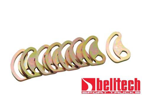
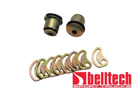
Belltech offers a 2* Camber Bushing Set (Part Number.4955) This kit includes (4) Upper Control Arm Offset Bushings.

You will need to press out your OE bushings and press in the new Belltech bushings. With the correct tools and patience this should take roughly about a hour and half or so to complete.
Here is a link to Belltech install notes if you want to read more on how to install
If you are still off on your alignment don't worry. Belltech also offers a 1* Cam Lock Plate Kit (Part Number 4951). You will need to remove the factory plate, elongate the opening and install the Belltech cam plate. With patience it should take about 45 mins or so.
Here is a link to Belltech install notes if you want to read more on how to install
You can also purchase the bushings and cam plates together with Part Number 4957
Here are a few examples of Kris' truck. This truck was lowered with about 4,000 miles on it. Now there is roughly 30,000 miles. Same suspension, wheels and tires. No rotation of tires either. There is roughly 80 % life left in these Falken Tires.


- Belltech 2" Drop Spindles Part Number 2511
- Belltech 2" Lowering Springs Part Number 12464
- Belltech Lowering Struts Part Number 25003
- Belltech 2* Camber Bushings Part Number 4955
- Belltech 1* Cam Plates Part Number 4951
- Belltech Front Sway Bar Part Number 5407
- Belltech 7" Flip Kit Part Number 6522
- Belltech 1" Lowering Shackle Part Number 6400
- Belltech Rear Street Performance Shocks Part Number 2208FF
- Belltech C Notch Part Number 6524
- Modified AirLift SlamAir Kit
- AirLift WirelessOne Part Number 25870
Tuesday, March 11, 2014
How to measure shocks
It's a pain in the butt trying to buy shocks for a truck/suv you bought lowered. Not knowing how much the truck is dropped makes buying shocks a difficult task. This how to will also be helpful for the trucks that have air suspension or running a super low static drop.
MEASURING POINTS FOR SHOCK ABSORBERS

*This is courtesy of KYB Americas website. We do not take credit for the images or text above.
MEASURING POINTS FOR SHOCK ABSORBERS
Measuring points differ based on the mounting style. Extended and Compressed lengths are measured:
- From center of eyering to shoulder of stud
- From center of eyering to center of eyering
- From shoulder of stud to shoulder of stud
*This is courtesy of KYB Americas website. We do not take credit for the images or text above.
Thursday, February 27, 2014
How To Measure for Wheel Spacers
Another question we get often from our coilover customers is " Which wheel spacers do I need? " This is another question we tend to back away from. Here is why: There are too many different wheel combinations. By combinations I mean offset, diameter and etc.
The guys over at H & R have put together a simple HOW TO to know you are ordering the right wheel spacers.
1. Gather Tools
To properly measure your wheel gap you will need a few simple tools:
2. Check Your Gap

Now that you have wheel spacers do not forget longer wheel bolts. Here is how to measure the bolts:

**Note content of this blog post is courtesy of H&R's website. We do not take credit for any of the photos,videos or text of the how to content.
The guys over at H & R have put together a simple HOW TO to know you are ordering the right wheel spacers.
1. Gather Tools
To properly measure your wheel gap you will need a few simple tools:
- Measuring device with millimeter units
- Straight edge--Yard stick or similar
2. Check Your Gap
- Place a straight edge flush with the face of the wheel and tire combination. Make sure the straight edge touches the tire in two spots to keep the straight edge even with the tire.
- Use the measuring device to measure from the inside of the straight edge to the inner fender lip. (see diagram)
- Make sure that the measurement is taken at the point where the wheel and tire is closest to the fender. For instance, on a car with a large amount of negative camber the tire and wheel may be closest at the front or rear edge of the fender.

Now that you have wheel spacers do not forget longer wheel bolts. Here is how to measure the bolts:
Here is a video courtesy of H&R
**Note content of this blog post is courtesy of H&R's website. We do not take credit for any of the photos,videos or text of the how to content.
Wednesday, February 26, 2014
How To Properly Measure Vehicle Ride Height
We often get the phone call or email saying "I don't know how much I want to lower my ride." The best way to get an idea is to measure.
Here is how to successfully do that:
1) Park your vehicle on a level surface. By doing this you ensure accurate results when getting the vehicle's ride height measurements
2) By using a measuring tape start from the center of the axle hub going straight up to the bottom of the fender lip.
3) Repeat this process for all four sides.

This is also a process we recommend BEFORE you install your lowered/lifted suspension. By having before and after measurements you can know the total actual amount of ride height you have achieved.
Now that you have figured out the ride height for your vehicle you want to know what size wheels and tires will work. We typically won't suggest a size to you unless we have personal experience with the same vehicle and suspension as you.
We do have a niffy tool from the guys over at Discount Tire to use. By using their Tire Dimensions tool you can see what tire size and rim will work. http://www.discounttire.com/dtcs/infoTireMath.dos
Ya we just gave you some homework, but hey look at it this way at least by doing the measurements we can ensure you order the right stuff the first time and will be happy with your new stance.
Here is how to successfully do that:
1) Park your vehicle on a level surface. By doing this you ensure accurate results when getting the vehicle's ride height measurements
2) By using a measuring tape start from the center of the axle hub going straight up to the bottom of the fender lip.
3) Repeat this process for all four sides.
This is also a process we recommend BEFORE you install your lowered/lifted suspension. By having before and after measurements you can know the total actual amount of ride height you have achieved.
Now that you have figured out the ride height for your vehicle you want to know what size wheels and tires will work. We typically won't suggest a size to you unless we have personal experience with the same vehicle and suspension as you.
We do have a niffy tool from the guys over at Discount Tire to use. By using their Tire Dimensions tool you can see what tire size and rim will work. http://www.discounttire.com/dtcs/infoTireMath.dos
Ya we just gave you some homework, but hey look at it this way at least by doing the measurements we can ensure you order the right stuff the first time and will be happy with your new stance.
Subscribe to:
Posts (Atom)